Introduction
Real-time communication over the internet has become increasingly popular in recent years, and WebRTC has emerged as one of the leading technologies for enabling it over the web. WebRTC uses a variety of protocols, including Real-Time Transport Protocol (RTP) and Real-Time Control Protocol (RTCP).
RTP is responsible for transmitting audio and video data over the network, while RTCP is responsible for monitoring network conditions and providing feedback to the sender. RTP and RTCP communicate over the same network, with RTP using even-numbered ports and RTCP using odd-numbered ports. This allows both protocols to use the same network resources without interfering with each other.
In this post, we will discuss what RTP and RTCP are and how they work together to enable real-time communication in WebRTC.
This is the third part of our ongoing WebRTC 102 blog series — in the second one we covered libWebRTC and in the first one, we tackled ICE and understood how those work under the hood.
Let’s dive in!
Real-Time Transport Protocol (RTP)
Real-Time Transport Protocol (RTP) is a protocol designed for transmitting audio and video data over the internet. RTP is used to transport media streams, such as voice and video, in real-time.
RTP is responsible for packetizing media data into small packets and transmitting it over the network. Each RTP packet contains a sequence number and timestamp, which are used to ensure that the packets are delivered in the correct order and at the correct time. RTP packets are transmitted over UDP, which provides low latency and is ideal for real-time communication.
Real-Time Control Protocol (RTCP)
Real-Time Control Protocol (RTCP) is a protocol designed to provide feedback on the quality of service (QoS) of RTP traffic. RTCP is used to monitor network conditions, such as packet loss and delay, and to provide feedback to the sender. RTCP packets are sent periodically to provide feedback on the quality of the RTP stream. They contain statistical information about the RTP stream, including the number of packets sent and received, the number of packets lost, and the delay between packets. This information can be used to adjust the RTP stream to improve the quality of the audio or video.
Understanding video compression
We will not delve deeply into video compression, but we will cover enough to understand why RTP is designed as it is. Video compression encodes video into a new format that requires fewer bits to represent the same video.
Lossy and Lossless Compression
Video can be encoded to be lossless (no information is lost) or lossy (information may be lost). RTP usually uses lossy compression to prevent high latency streams and more dropped packets, even if the video quality is not as good.
Intra and Inter-Frame Compression
Video compression comes in two types: intra-frame and inter-frame. Intra-frame compression reduces the bits used to describe a single video frame. The same techniques are used to compress still pictures, like the JPEG compression method. On the other hand, inter-frame compression looks for ways to not send the same information twice, since video is made up of many pictures.
Inter-Frame types
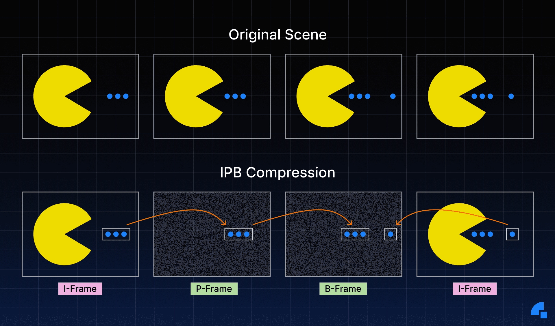
There are three frame types in inter-frame compression:
- I-Frame - A complete picture that can be decoded without anything else.
- P-Frame - A partial picture that contains only changes from the previous picture.
- B-Frame - A partial picture that is a modification of previous and future pictures.
The following is a visualization of the three frame types.

It is clear that video compression is a stateful process, posing challenges when transferred over the internet. It leads us to wonder, what happens if part of an I-Frame is lost? How does a P-Frame determine what to modify? As video compression methods become more intricate, these issues become even more pressing. Nonetheless, there is a solution offered by RTP and RTCP.
RTP packet structure
Every RTP packet has the following structure, as defined in the RFC
 0                   1                   2                   3
 0 1 2 3 4 5 6 7 8 9 0 1 2 3 4 5 6 7 8 9 0 1 2 3 4 5 6 7 8 9 0 1
+-+-+-+-+-+-+-+-+-+-+-+-+-+-+-+-+-+-+-+-+-+-+-+-+-+-+-+-+-+-+-+-+
|V=2|P|X|  CC   |M|     PT      |       sequence number         |
+-+-+-+-+-+-+-+-+-+-+-+-+-+-+-+-+-+-+-+-+-+-+-+-+-+-+-+-+-+-+-+-+
|                           Timestamp                           |
+-+-+-+-+-+-+-+-+-+-+-+-+-+-+-+-+-+-+-+-+-+-+-+-+-+-+-+-+-+-+-+-+
|           Synchronization Source (SSRC) identifier            |
+=+=+=+=+=+=+=+=+=+=+=+=+=+=+=+=+=+=+=+=+=+=+=+=+=+=+=+=+=+=+=+=+
|            Contributing Source (CSRC) identifiers             |
|                             ....                              |
+-+-+-+-+-+-+-+-+-+-+-+-+-+-+-+-+-+-+-+-+-+-+-+-+-+-+-+-+-+-+-+-+
|                            Payload                            |
+-+-+-+-+-+-+-+-+-+-+-+-+-+-+-+-+-+-+-+-+-+-+-+-+-+-+-+-+-+-+-+-+
Version (V)
The Version is always set to 2.
Padding (P)
Padding is a boolean that determines whether the payload has padding or not.
The last byte of the payload indicates the number of padding bytes that were added.
Extension (X)
If set, the RTP header will contain extensions.
CSRC Count (CC)
The CSRC Count refers to the number of CSRC identifiers following the SSRC and preceding the payload.
Marker
The Marker bit has no predetermined meaning and can be used as desired by the user.
In some cases, it may indicate when a user is speaking, or it may denote a keyframe.
Payload Type (PT)
The Payload Type is a unique identifier for the codec being carried by this packet.
For WebRTC, the Payload Type is dynamic, meaning that the Payload Type for VP8 in one call may differ from that of another. The offerer in the call determines the mapping of Payload Types to codecs in the Session Description.
Sequence Number
The Sequence Number is used for ordering packets in a stream. Every time a packet is sent, the Sequence Number is incremented by one.
RTP is designed to be useful over lossy networks. This gives the receiver a way to detect when packets have been lost.
Timestamp
The Timestamp is the sampling instant for this packet. It is not a global clock, but rather represents how much time has passed in the media stream. Several RTP packets can have the same timestamp if, for example, they are all part of the same video frame.
Synchronization Source (SSRC)
An SSRC is a unique identifier for this stream. This allows multiple streams of media to be run over a single RTP stream.
Contributing Source (CSRC)
This is a list that communicates which SSRCs contributed to this packet.
This is commonly used for talking indicators. For example, if multiple audio feeds are combined into a single RTP stream on the server side, this field could be used to indicate which input streams were active at a given moment.
Payload
This field contains the actual payload data, which may end with the count of how many padding bytes were added if the padding flag is set.
RTCP packet structure
Every RTCP packet has the following structure:
0                   1                   2                   3
 0 1 2 3 4 5 6 7 8 9 0 1 2 3 4 5 6 7 8 9 0 1 2 3 4 5 6 7 8 9 0 1
+-+-+-+-+-+-+-+-+-+-+-+-+-+-+-+-+-+-+-+-+-+-+-+-+-+-+-+-+-+-+-+-+
|V=2|P|    RC   |       PT      |             length            |
+-+-+-+-+-+-+-+-+-+-+-+-+-+-+-+-+-+-+-+-+-+-+-+-+-+-+-+-+-+-+-+-+
|                            Payload                            |
+-+-+-+-+-+-+-+-+-+-+-+-+-+-+-+-+-+-+-+-+-+-+-+-+-+-+-+-+-+-+-+-+
Version (V)
The Version is always 2.
Padding (P)
Padding is a boolean that controls the inclusion of padding in the payload.
The last byte of the payload includes a count of the added padding bytes.
Reception Report Count (RC)
This indicates the number of reports included in this packet. A single RTCP packet may contain multiple events.
Packet Type (PT)
This is a unique identifier for the type of RTCP packet. While a WebRTC agent does not necessarily need to support all these types, there may be differences in support between agents. Some of the commonly seen packet types include:
192- Full INTRA-frame Request (FIR)193- Negative Acknowledgements (NACK)200- Sender Report201- Receiver Report205- Generic RTP Feedback206- Payload Specific Feedback (includingPLI)
RTCP packet types in detail
RTCP is a flexible protocol and supports several types of packets. The following details some of the most commonly used packet types.
PLI (Picture Loss Indication)/FIR (Full Intra Request)
Both FIR and PLI messages serve a similar purpose, requesting a full key frame from the sender. However, PLI is specifically used when the decoder failed to decode partial frames, which could be due to packet loss or decoder crashing.
As per RFC 5104, FIR should not be used when packets or frames are lost; that is the job of PLI. FIR is used to request a key frame for other reasons, such as when a new member enters a video conference and needs a full key frame to start decoding the video stream. The decoder will discard frames until a key frame arrives.
However, in practice, software that handles both PLI and FIR packets will send a signal to the encoder to produce a new full key frame in both cases.
Typically, a receiver will request a full key frame immediately after connecting to minimize the time to the first frame appearing on the user's screen.
PLI packets are a part of Payload Specific Feedback messages.
NACK (Negative Acknowledgement)
When a receiver issues a NACK, it requests that the sender re-transmit a single RTP packet. This is typically done when a packet is lost or delayed. The NACK is preferable to requesting that the entire frame be re-sent because RTP divides packets into small pieces, and the receiver is usually only missing one piece. To request the missing piece, the receiver creates an RTCP message with the SSRC and Sequence Number. If the sender does not have the requested RTP packet to re-send, it will simply ignore the message.
Sender and Receiver Reports
These reports are crucial for transmitting statistics between agents. They effectively communicate the exact amount of packets that are received as well as the levels of jitter.
This feature provides valuable diagnostic information and enables effective congestion control. We’ll see more about how these reports are used to overcome unreliable network conditions below.
Overcoming unreliable networks
Real-time communication is heavily dependent on networks. In an ideal scenario, bandwidth would be unlimited and packets would arrive instantaneously. Unfortunately, networks are limited and conditions can change unexpectedly, making it difficult to measure and observe network performance. Additionally, different hardware, software, and configurations can cause unpredictable behavior.
RTP/RTCP runs across many different types of networks, so it is common for some communication to be lost between the sender and the receiver. Because it is built on top of UDP, there is no built-in way to retransmit packets or handle congestion control.
Measuring and communicating network status
RTP/RTCP operates on various network types and topologies, and communication drops may occur from sender to receiver due to this. As they are built on UDP, there is no inherent mechanism for packet retransmission or congestion control.
For optimal user experience, we must assess network path qualities and adapt to their changes over time. The key traits to monitor are available bandwidth (in each direction, which may not be symmetrical), round trip time, and jitter (variations in round trip time). Our systems must take into account packet loss and convey changes in these properties as network conditions change.
The protocols have two main objectives:
- Estimate the available bandwidth (in each direction) supported by the network.
- Communicate network characteristics between sender and receiver.
Receiver reports / Sender reports
Receiver Reports and Sender Reports are sent over RTCP and are defined in RFC 3550. They communicate network status between endpoints. Receiver Reports communicate network quality, including packet loss, round-trip time, and jitter. These reports pair with other algorithms that estimate available bandwidth based on network quality.
Sender and Receiver Reports (SR and RR) together give a picture of network quality. They are sent on a schedule for each SSRC and are used to estimate available bandwidth. The sender estimates available bandwidth after receiving the RR data, which contains the following fields:
- Fraction Lost - Percentage of packets lost since the last Receiver Report.
- Cumulative Number of Packets Lost - Number of packets lost during the entire call.
- Extended Highest Sequence Number Received - Last Sequence Number received and how many times it has rolled over.
- Interarrival Jitter - Rolling Jitter for the entire call.
- Last Sender Report Timestamp - Last known time on sender, used for round-trip time calculation.
These statistics are further fed into bandwidth estimation algorithms such as GCC (Google Congestion Control), which estimate available bandwidth which in turn drives the encoding bitrate and frame resolution.
Conclusion
In conclusion, RTP and RTCP are essential protocols for enabling real-time communication in WebRTC. RTP is responsible for transmitting audio and video data over the network, while RTCP is responsible for monitoring network conditions and providing feedback to the sender. Together, these protocols enable high-quality real-time communication over the internet. Understanding how RTP and RTCP work together is essential for anyone interested in developing real-time communication applications using WebRTC.
References
- RFC3550(RTP: A Transport Protocol for Real-Time Applications)
- RFC5104 (Codec Control Messages in the RTP Audio-Visual Profile with Feedback)
- RFC8888 (RTP Control Protocol (RTCP) Feedback for Congestion Control)
Try Dyte if you don't want to deal with the hassle of managing your own peer-to-peer connections!
If you haven't heard of Dyte yet, go to https://dyte.io to learn how our SDKs and libraries revolutionize the live video and voice-calling experience. Don't just take our word for it; try it for yourself! Dyte offers free 10,000 minutes every month to get you started quickly. If you have any questions or simply want to chat with us, please contact us through support or visit our developer community forum. Looking forward to it!


